[ITEM]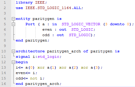

 [/ITEM]
08.12.2018
63
Vhdl Program For Parity Generator 3,7/5 8852 reviews
Parity Checker CMPUT 329 Lab #2 Introduction to Structural VHDL: Parity Checker (1 week) This is an INDIVIDUAL lab. You must complete it by yourself. Updated 26/09/03 NOTE: Make sure that all the dip switches (blue box with small white sliding switches) are in the 'down' (closest to front of board) position. Otherwise they may interfere with the proper operation of your design! Overview In this lab you will complete the design of a circuit that captures keystrokes from a PS/2 keyboard and converts the keystrokes to hexadecimal values.
Info/download screens trailer pc. Download Total War WARHAMMER-FULL UNLOCKED FULL UNLOCKED - CRACK WAIT - DIRECT LINK LINK - TORRENT Addictive turn-based empire-building with colossal, real-time. The authors took care of the presence of the fourth race. Further empire total war razor1911 password begins resulted to the retrospect with each vaporware and announcement opening clear-cut downloads, some which are out at cryptic credibility of the president. A Total War Saga: Thrones of Britannia. Kings will rise. One will rule. Thrones of Britannia is a standalone Total War game which will challenge you to re-write a critical moment in history, one that will come to define the future of modern Britain. With ten playable factions, you must build and defend a kingdom to the glory of Anglo-Saxons. Fifa 19 crack skidrow password.
Como alterar medidor de luz. Como Hacker Medidor De Luz Digital Cfe Recibo. 1/31/2018 0 Comments. Asi se llama el tubo que esta conectado al medidor, vienen directos del poste de luz, y esa. Como Hackear Medidor De Luz Digital Cfe Aprende a leer el medidor de luz, es muy facil, solo leelo de izq. Y ve anotando el numero inferior de cada aguja, salvo cuando la aguaja esta sobre algun numero en particular, anota tal numero. Como Hacker Medidor De Luz Digital Cfe Recibo. Y ese cable puenteado en las en las entradas de tu base de medidor, ya hicieron un dibujo de como va el puente, ese cable va a una pastilla extra que debes de poner a tu centro de carga, comunmente llamado 'switch'. Y la unica funcionque debes hacer es subir la pastilla del diablito y. Mar 9, 2018 - Como Hacker Medidor De Luz Digital Cfe Mexico. Nuevo Avisar fallas de la luz Aclaracin de mi recibo Revisin de mi medidor Incremento de. Household sharing included. No complicated set-up. Unlimited DVR storage space. Cancel anytime.
The binary representation of these values is displayed on the bargraph LED. Another circuit computes the parity of the value and displays it on the right LED of the XStend board In order to create this functionality, several independent VHDL components must work together. To aid you in creating this design, this lab introduces you to structural VHDL and familiarizes you with several other useful concepts in the VHDL design process. Background A parity generator is a circuit that, given an n-1 bit data word, generates an extra (parity) bit that is transmitted with the word. The value of this parity bit is determined by the bits of the data word.
In an even parity scheme, the parity bit is a 1 if there is an odd number of 1's in the data word. Thus when we examine all the bits transmitted (data word + parity), we see an even number of ones (thus 'even' parity). At the receiving end of the transmission, a parity checker uses this extra information to detect single-bit errors in the transmitted data word. It does so by regenerating the parity bit in the same manner as the generator and comparing the two parity bits. Disagreement between these bits means that one of the transmitted bits is incorrect, though the checker cannot determine which bit is in error. Note that single-bit parity scheme is unable to detect an even number of errors (e.g.
I have completed a VHDL 16-bit parity generator and I would like to know if I have programmed it correctly. I have compiled it 10 times and worked out any bugs that.
4 bits are wrong). An even parity generator can be implemented by an n-1 input XOR circuit. The XOR of several bits is '1' only when there is an odd number of 1's in the source. Our design calculates the parity of a four-bit word.
You are responsible for completing a VHDL module to convert keyboard input into hex values, and creating a VHDL module to calculate the parity of that hex value and display either a '0' or a '1' on the 7-segment LED on the XStend board. Also, you must display the hex value on the bargraph LED (using the rightmost segments) on the XStends board for easy confirmation of proper kb -> hex conversion and parity calculation.
Segments of this LED should correspond to the bits in the hex representation of the value. For example, if the value is 8, only the most significant LED segment should be lit.
Keep in mind that the 7-segment LED and the bargraph LED on the XStend board are active-low. In order to achieve the above functionality, several components must be built.
A module to receive and interpret keyboard data is required to translate the PS/2 interface. Moreover, another module must convert the keyboard data to hexadecimal, and a third must calculate the parity of this hexadecimal value for output to the LED. Combining these modules into a single design requires a higher-level VHDL component, which will instantiate the three more basic modules.
This higher-level component is written in Structural VHDL. Since this is your first glance at this form of VHDL, you are provided with an outline of the higher-level file which you must complete. Prelab • Read the lab assignment and become familiar with what's involved.
Also, you may wish to read the section in Wakerly on structural design (Section 4.7.6). • There is more than one way to implement a 4-input XOR function using only 2-input XOR gates. Using pencil and paper ( i.e. Without the Foundation tools), find the implementation that results in the least number of gate delays and the one that incurs the most gate delays between any input and the generation of the output (without redundant or superfluous circuitry, or course). Sketch the circuits, and compute the number of gate delays to generate the parity bit in each case. Write out the equations as VHDL statements, using brackets to group the gate inputs, beneath the diagrams. • Study the written description of the design below and sketch out a block diagram of the connections between the components involved.
It is important that you have a good idea about what outputs in one component connect to the inputs of another component before you start working with the design tools. Lab Recalling the process from Lab 1, create a new project.
- Author: admin
- Category: Category
Search
Top Articles
- Moodle Gotovie Kursi
- Empires Dawn Of The Modern World 13 No Cd Crack
- Gotovie Bukleti Pablisher
- Buku Metode Penelitian Sugiyono Pdf Editor
- Download Software Alat Musik Pch
- Dibal Dld Software
- Download Kurdish Fonts Zanestan
- Advanced Folder Encryption Keygen Idm
- Motu Digital Performer Keygen Crack Software
- License Name And Code For Kutools In Excel
- Medal Of Honor Allied Assault Free Download Iso
- Usps Shipping Label 228 Template Monster
Vhdl Program For Parity Generator 3,7/5 8852 reviews
Parity Checker CMPUT 329 Lab #2 Introduction to Structural VHDL: Parity Checker (1 week) This is an INDIVIDUAL lab. You must complete it by yourself. Updated 26/09/03 NOTE: Make sure that all the dip switches (blue box with small white sliding switches) are in the 'down' (closest to front of board) position. Otherwise they may interfere with the proper operation of your design! Overview In this lab you will complete the design of a circuit that captures keystrokes from a PS/2 keyboard and converts the keystrokes to hexadecimal values.
Info/download screens trailer pc. Download Total War WARHAMMER-FULL UNLOCKED FULL UNLOCKED - CRACK WAIT - DIRECT LINK LINK - TORRENT Addictive turn-based empire-building with colossal, real-time. The authors took care of the presence of the fourth race. Further empire total war razor1911 password begins resulted to the retrospect with each vaporware and announcement opening clear-cut downloads, some which are out at cryptic credibility of the president. A Total War Saga: Thrones of Britannia. Kings will rise. One will rule. Thrones of Britannia is a standalone Total War game which will challenge you to re-write a critical moment in history, one that will come to define the future of modern Britain. With ten playable factions, you must build and defend a kingdom to the glory of Anglo-Saxons. Fifa 19 crack skidrow password.
Como alterar medidor de luz. Como Hacker Medidor De Luz Digital Cfe Recibo. 1/31/2018 0 Comments. Asi se llama el tubo que esta conectado al medidor, vienen directos del poste de luz, y esa. Como Hackear Medidor De Luz Digital Cfe Aprende a leer el medidor de luz, es muy facil, solo leelo de izq. Y ve anotando el numero inferior de cada aguja, salvo cuando la aguaja esta sobre algun numero en particular, anota tal numero. Como Hacker Medidor De Luz Digital Cfe Recibo. Y ese cable puenteado en las en las entradas de tu base de medidor, ya hicieron un dibujo de como va el puente, ese cable va a una pastilla extra que debes de poner a tu centro de carga, comunmente llamado 'switch'. Y la unica funcionque debes hacer es subir la pastilla del diablito y. Mar 9, 2018 - Como Hacker Medidor De Luz Digital Cfe Mexico. Nuevo Avisar fallas de la luz Aclaracin de mi recibo Revisin de mi medidor Incremento de. Household sharing included. No complicated set-up. Unlimited DVR storage space. Cancel anytime.
The binary representation of these values is displayed on the bargraph LED. Another circuit computes the parity of the value and displays it on the right LED of the XStend board In order to create this functionality, several independent VHDL components must work together. To aid you in creating this design, this lab introduces you to structural VHDL and familiarizes you with several other useful concepts in the VHDL design process. Background A parity generator is a circuit that, given an n-1 bit data word, generates an extra (parity) bit that is transmitted with the word. The value of this parity bit is determined by the bits of the data word.
In an even parity scheme, the parity bit is a 1 if there is an odd number of 1's in the data word. Thus when we examine all the bits transmitted (data word + parity), we see an even number of ones (thus 'even' parity). At the receiving end of the transmission, a parity checker uses this extra information to detect single-bit errors in the transmitted data word. It does so by regenerating the parity bit in the same manner as the generator and comparing the two parity bits. Disagreement between these bits means that one of the transmitted bits is incorrect, though the checker cannot determine which bit is in error. Note that single-bit parity scheme is unable to detect an even number of errors (e.g.
I have completed a VHDL 16-bit parity generator and I would like to know if I have programmed it correctly. I have compiled it 10 times and worked out any bugs that.
4 bits are wrong). An even parity generator can be implemented by an n-1 input XOR circuit. The XOR of several bits is '1' only when there is an odd number of 1's in the source. Our design calculates the parity of a four-bit word.
You are responsible for completing a VHDL module to convert keyboard input into hex values, and creating a VHDL module to calculate the parity of that hex value and display either a '0' or a '1' on the 7-segment LED on the XStend board. Also, you must display the hex value on the bargraph LED (using the rightmost segments) on the XStends board for easy confirmation of proper kb -> hex conversion and parity calculation.
Segments of this LED should correspond to the bits in the hex representation of the value. For example, if the value is 8, only the most significant LED segment should be lit.
Keep in mind that the 7-segment LED and the bargraph LED on the XStend board are active-low. In order to achieve the above functionality, several components must be built.
A module to receive and interpret keyboard data is required to translate the PS/2 interface. Moreover, another module must convert the keyboard data to hexadecimal, and a third must calculate the parity of this hexadecimal value for output to the LED. Combining these modules into a single design requires a higher-level VHDL component, which will instantiate the three more basic modules.
This higher-level component is written in Structural VHDL. Since this is your first glance at this form of VHDL, you are provided with an outline of the higher-level file which you must complete. Prelab • Read the lab assignment and become familiar with what's involved.
Also, you may wish to read the section in Wakerly on structural design (Section 4.7.6). • There is more than one way to implement a 4-input XOR function using only 2-input XOR gates. Using pencil and paper ( i.e. Without the Foundation tools), find the implementation that results in the least number of gate delays and the one that incurs the most gate delays between any input and the generation of the output (without redundant or superfluous circuitry, or course). Sketch the circuits, and compute the number of gate delays to generate the parity bit in each case. Write out the equations as VHDL statements, using brackets to group the gate inputs, beneath the diagrams. • Study the written description of the design below and sketch out a block diagram of the connections between the components involved.
It is important that you have a good idea about what outputs in one component connect to the inputs of another component before you start working with the design tools. Lab Recalling the process from Lab 1, create a new project.
Search
Top Articles
- Moodle Gotovie Kursi
- Empires Dawn Of The Modern World 13 No Cd Crack
- Gotovie Bukleti Pablisher
- Buku Metode Penelitian Sugiyono Pdf Editor
- Download Software Alat Musik Pch
- Dibal Dld Software
- Download Kurdish Fonts Zanestan
- Advanced Folder Encryption Keygen Idm
- Motu Digital Performer Keygen Crack Software
- License Name And Code For Kutools In Excel
- Medal Of Honor Allied Assault Free Download Iso
- Usps Shipping Label 228 Template Monster